Not sure if this under the right heading! I have just purchased a Seep PM2 "point motor" and am a little confused. The instructions say that it can either be mounted under the baseboard or alongside the track, not sure how this can be??
Any help gratefully received.
John
Point motor
-
Walkingthedog

- Posts: 5119
- Joined: Thu Oct 04, 2018 5:51 pm
- Location: HAZLEMERE, BUCKS.
- Contact:

Re: Point motor
LOCATING YOUR SEEP POINT MOTOR
Your SEEP point motor can be fitted adjacent to your track or
beneath your baseboard.
To fit beneath your baseboard temporarily secure the point in what
will be its final position. Move the point tie bar to a position that
equates to half the distance of its travel. Using a fine drill and the
linkage hole as your guide carefully drill vertically down through the
baseboard. Remove the point from your baseboard. Using a 1mm
drill bit expand the pilot hole. From beneath the baseboard insert
the point motor operating rod. Rotate the main body of the point
motor so that its direction of operation is along the axis of the point
tie bar. Move the body of the point motor so that its operating rod is
half way between the two point motor coils (a small piece of stiff
card 9.5 wide with a 1mm wide slot cut along its centre line and
inserted between the point motor coils may help you do this) and
secure the point motor to the base board using the two fixing holes
provided. Remove the point motor and expand the centre pilot hole
to a diameter slightly greater than the travel of the point tie bar.
Before finally reaffixing your point motor you may elect to fit ‘flying
leads’ to its terminals. Prior to finally positioning and securing the
point motor trim the actuating rod to suit. Reaffix the point motor.
That is from the Gaugemaster instructions, no mention how to fix adjacent to track!!!!
I have installed about 5 of these under the baseboard, a bit fiddly to fit and get right, also the frog switching is not great.
Replace all mine with Peco surface mounted motors.
Sorry that does not help you, but no doubt someone will know how to mount them.
Forfarian aka Tim
Of course I talk to myself, I sometimes need expert advice!
Of course I talk to myself, I sometimes need expert advice!

Re: Point motor
Hi
Here is my take on how I have installed Seep PMx range under the baseboard. The main thing to remember is they are notorious for needing to be installed in line with the point above. I've never seen one above board mounted but I'm guessing that the motor would have to be fixed on two L brackets and be sideways on to the baseboard, the drive rod then linked to the point stretcher bar by plastic rod or metal rod somehow??
Note the PM2 motor doesn't have any change over switching. Only the PM1 and PM4 have the on board switch.
This is how I fix them to ensure the Seep is correctly fitted underneath the layout….
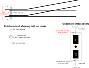
Lay point in its final position but do not fix it down. Hold the points moving stretcher bar in the central mid-way position and mark through the drive pin hole onto the baseboard top. Allow the points stretcher bar to move over and mark on the baseboard the exact centre line of the stretcher bar. Move point to the opposite direction and again mark that sides dead centre of the stretcher. Lift points and where the drive pin mark was made drill out a hole with either a 9mm dia bit or use a 4mm bit and drill two holes side by side then elongate them into a slot approx. 4mm x 9mm. Change drill bit to a 1mm one and where you marked the outer positions of the stretcher bar drill a hole on that line on each side - two holes of 1mm each outside of the footprint of the point. Now underneath the baseboard and with a pencil and rule, draw a straight line linking the two 1mm holes drilled previously. The line should also pass through the centre of the drive pin hole too. Make sure you extend the pencil line out beyond the 1mm holes by some 10mm to 20mm on each side. Now take the Seep motor and mark on its PCB its exact drive pin centre line, doing this on each side. Pre wire the motor if desired, as its easier to solder short lengths of wire (tails) onto its pads on the workbench rather than doing it upside down! These wire tails can be about 4”-6” inches long and they terminate in a three way piece of terminal block. Make sure “C” (Return pad) is on the outside of the three way, so as “A” & “B” pads are in positions 1 and 2 of the terminal block. Fix down the point so as it aligns with the holes drilled and its stretcher bar is in line with the 1mm holes.
Once the point is fixed down and before the motor is offered up, I place two “Wedges” in the point blades so as the point blades are held central (Wedges are just something suitable - bits of wire, matchsticks or whatever you have to hand) When fitting the PMx motor again keep it central/mid throw position. Then once fitted your motor and point will be equal for each direction of motor throw. Otherwise you are likely to install the motor more towards one way and that leads to operating problems.
Underneath carefully fit the motor so as its drive pin passes up through the points drive pin hole in the stretcher bar. Now I try and get some help, as a wooded clothes peg or Bulldog clip is clamped to the Seeps drive pin above the point holding the motor in position until its screwed in place. Carefully secure the motor with small wood screws, but ensure the previously marked motors centre is directly in line with the drawn pencil line. Do not over tighten the securing screws. Remove the peg or Bulldog clip and by hand underneath move the Seeps drive pin over to both directions the point should follow and there shouldn’t be any resistance felt other than the points over centre spring pressure. Assuming all is good secure three way terminal block and connect the two wires into the blocks 1 & 2 terminal coming from the switch or lever. Connect the one common return wire into the 3rd terminal position. Power up and allow CDU a second or two to reach fully charged and then operate the point switch or lever for that point. It should “Pop” over each way with the switch but do all. Cut the overly long drive pin off as near to flush with the top of the stretcher bar as possible. I use a old pair of largish side cutters and never use a Dremel as the heat caused can damage the plastic stretcher bar. There are also available special hard wire cutters but they tend to be expensive! A cheap pair of Pound shop or market stall wire cutters will do the job. Mine are 7inch type. Watch out for flying cut off pin ends though!
The above is a copy of an email I sent to a contact a while ago, so I haven't spent ages typing it today!
Here is my take on how I have installed Seep PMx range under the baseboard. The main thing to remember is they are notorious for needing to be installed in line with the point above. I've never seen one above board mounted but I'm guessing that the motor would have to be fixed on two L brackets and be sideways on to the baseboard, the drive rod then linked to the point stretcher bar by plastic rod or metal rod somehow??
Note the PM2 motor doesn't have any change over switching. Only the PM1 and PM4 have the on board switch.
This is how I fix them to ensure the Seep is correctly fitted underneath the layout….
Lay point in its final position but do not fix it down. Hold the points moving stretcher bar in the central mid-way position and mark through the drive pin hole onto the baseboard top. Allow the points stretcher bar to move over and mark on the baseboard the exact centre line of the stretcher bar. Move point to the opposite direction and again mark that sides dead centre of the stretcher. Lift points and where the drive pin mark was made drill out a hole with either a 9mm dia bit or use a 4mm bit and drill two holes side by side then elongate them into a slot approx. 4mm x 9mm. Change drill bit to a 1mm one and where you marked the outer positions of the stretcher bar drill a hole on that line on each side - two holes of 1mm each outside of the footprint of the point. Now underneath the baseboard and with a pencil and rule, draw a straight line linking the two 1mm holes drilled previously. The line should also pass through the centre of the drive pin hole too. Make sure you extend the pencil line out beyond the 1mm holes by some 10mm to 20mm on each side. Now take the Seep motor and mark on its PCB its exact drive pin centre line, doing this on each side. Pre wire the motor if desired, as its easier to solder short lengths of wire (tails) onto its pads on the workbench rather than doing it upside down! These wire tails can be about 4”-6” inches long and they terminate in a three way piece of terminal block. Make sure “C” (Return pad) is on the outside of the three way, so as “A” & “B” pads are in positions 1 and 2 of the terminal block. Fix down the point so as it aligns with the holes drilled and its stretcher bar is in line with the 1mm holes.
Once the point is fixed down and before the motor is offered up, I place two “Wedges” in the point blades so as the point blades are held central (Wedges are just something suitable - bits of wire, matchsticks or whatever you have to hand) When fitting the PMx motor again keep it central/mid throw position. Then once fitted your motor and point will be equal for each direction of motor throw. Otherwise you are likely to install the motor more towards one way and that leads to operating problems.
Underneath carefully fit the motor so as its drive pin passes up through the points drive pin hole in the stretcher bar. Now I try and get some help, as a wooded clothes peg or Bulldog clip is clamped to the Seeps drive pin above the point holding the motor in position until its screwed in place. Carefully secure the motor with small wood screws, but ensure the previously marked motors centre is directly in line with the drawn pencil line. Do not over tighten the securing screws. Remove the peg or Bulldog clip and by hand underneath move the Seeps drive pin over to both directions the point should follow and there shouldn’t be any resistance felt other than the points over centre spring pressure. Assuming all is good secure three way terminal block and connect the two wires into the blocks 1 & 2 terminal coming from the switch or lever. Connect the one common return wire into the 3rd terminal position. Power up and allow CDU a second or two to reach fully charged and then operate the point switch or lever for that point. It should “Pop” over each way with the switch but do all. Cut the overly long drive pin off as near to flush with the top of the stretcher bar as possible. I use a old pair of largish side cutters and never use a Dremel as the heat caused can damage the plastic stretcher bar. There are also available special hard wire cutters but they tend to be expensive! A cheap pair of Pound shop or market stall wire cutters will do the job. Mine are 7inch type. Watch out for flying cut off pin ends though!
The above is a copy of an email I sent to a contact a while ago, so I haven't spent ages typing it today!
 << Click the Icon to go to my website
-
Walkingthedog
- Posts: 5119
- Joined: Thu Oct 04, 2018 5:51 pm
- Location: HAZLEMERE, BUCKS.
- Contact:
Re: Point motor
But how about alongside the track Brian. Is there an adapter the motor fits to much like Peco motors?
Nurse, the screens!

Re: Point motor
https://www.ebay.co.uk/itm/Point-Motor- ... SwoWBgG~N1
This may be what is needed - it is 3D printed - although I've not tried them.
This may be what is needed - it is 3D printed - although I've not tried them.
Re: Point motor
Ive never seen any above board adaptor? My first paragraph guesses at how it might be fixed surface??Walkingthedog wrote: ↑Wed Feb 17, 2021 3:35 pm But how about alongside the track Brian. Is there an adapter the motor fits to much like Peco motors?
Below shows what I mean for my below baseboard fitting text above...
 << Click the Icon to go to my website
-
Walkingthedog
- Posts: 5119
- Joined: Thu Oct 04, 2018 5:51 pm
- Location: HAZLEMERE, BUCKS.
- Contact:
Re: Point motor
I stand corrected Brian re PM2 being a frog change over switch. slaps handBrian wrote: ↑Wed Feb 17, 2021 3:30 pm Hi
Here is my take on how I have installed Seep PMx range under the baseboard. The main thing to remember is they are notorious for needing to be installed in line with the point above. I've never seen one above board mounted but I'm guessing that the motor would have to be fixed on two L brackets and be sideways on to the baseboard, the drive rod then linked to the point stretcher bar by plastic rod or metal rod somehow??
Note the PM2 motor doesn't have any change over switching. Only the PM1 and PM4 have the on board switch.
This is how I fix them to ensure the Seep is correctly fitted underneath the layout….
Lay point in its final position but do not fix it down. Hold the points moving stretcher bar in the central mid-way position and mark through the drive pin hole onto the baseboard top. Allow the points stretcher bar to move over and mark on the baseboard the exact centre line of the stretcher bar. Move point to the opposite direction and again mark that sides dead centre of the stretcher. Lift points and where the drive pin mark was made drill out a hole with either a 9mm dia bit or use a 4mm bit and drill two holes side by side then elongate them into a slot approx. 4mm x 9mm. Change drill bit to a 1mm one and where you marked the outer positions of the stretcher bar drill a hole on that line on each side - two holes of 1mm each outside of the footprint of the point. Now underneath the baseboard and with a pencil and rule, draw a straight line linking the two 1mm holes drilled previously. The line should also pass through the centre of the drive pin hole too. Make sure you extend the pencil line out beyond the 1mm holes by some 10mm to 20mm on each side. Now take the Seep motor and mark on its PCB its exact drive pin centre line, doing this on each side. Pre wire the motor if desired, as its easier to solder short lengths of wire (tails) onto its pads on the workbench rather than doing it upside down! These wire tails can be about 4”-6” inches long and they terminate in a three way piece of terminal block. Make sure “C” (Return pad) is on the outside of the three way, so as “A” & “B” pads are in positions 1 and 2 of the terminal block. Fix down the point so as it aligns with the holes drilled and its stretcher bar is in line with the 1mm holes.
Once the point is fixed down and before the motor is offered up, I place two “Wedges” in the point blades so as the point blades are held central (Wedges are just something suitable - bits of wire, matchsticks or whatever you have to hand) When fitting the PMx motor again keep it central/mid throw position. Then once fitted your motor and point will be equal for each direction of motor throw. Otherwise you are likely to install the motor more towards one way and that leads to operating problems.
Underneath carefully fit the motor so as its drive pin passes up through the points drive pin hole in the stretcher bar. Now I try and get some help, as a wooded clothes peg or Bulldog clip is clamped to the Seeps drive pin above the point holding the motor in position until its screwed in place. Carefully secure the motor with small wood screws, but ensure the previously marked motors centre is directly in line with the drawn pencil line. Do not over tighten the securing screws. Remove the peg or Bulldog clip and by hand underneath move the Seeps drive pin over to both directions the point should follow and there shouldn’t be any resistance felt other than the points over centre spring pressure. Assuming all is good secure three way terminal block and connect the two wires into the blocks 1 & 2 terminal coming from the switch or lever. Connect the one common return wire into the 3rd terminal position. Power up and allow CDU a second or two to reach fully charged and then operate the point switch or lever for that point. It should “Pop” over each way with the switch but do all. Cut the overly long drive pin off as near to flush with the top of the stretcher bar as possible. I use a old pair of largish side cutters and never use a Dremel as the heat caused can damage the plastic stretcher bar. There are also available special hard wire cutters but they tend to be expensive! A cheap pair of Pound shop or market stall wire cutters will do the job. Mine are 7inch type. Watch out for flying cut off pin ends though!
The above is a copy of an email I sent to a contact a while ago, so I haven't spent ages typing it today!
Forfarian aka Tim
Of course I talk to myself, I sometimes need expert advice!
Of course I talk to myself, I sometimes need expert advice!