I would like to control a double header light signal with the above. Now Gaugemaster says I would need two GM500 to do this.
I assume this is because there are two LED's running at the same time. Now when I wire LED's to light my buildings up, if I have
two LED's running together on the same wire, I just use a different double resistor, of which I have none left.
Would changing the resistor in the GM500 work the same?
Now I don't know what the different values are, but someone could probably tell me.
Why they did not make the thing to work with a double header in the first place, I can't understand, it would seem logical to me
to do this, as junction signals tend, I would think, to be double headers, or am I wrong on that assumption, or is it made so to make you buy two.
This is the first time I have fitted such a signal to my layout, at the moment I use a toggle switch to change the signal, but it would
be cool to have this done by the point.
Sorry for waffling on a bit.
Gaugemaster GM500 upgrade?
-
airfix27ra

- Posts: 54
- Joined: Sat Apr 25, 2020 12:36 pm
- Contact:
Gaugemaster GM500 upgrade?
Love, Peace and Happiness.
Old Hippies never die, we just float away.
Have a cup of tea. reference to Gong.
Old Hippies never die, we just float away.
Have a cup of tea. reference to Gong.

Re: Gaugemaster GM500 upgrade?
Hi,
When you say a 'double header' light signal, what do you mean?
The GM500 is a DPDT relay, which means it's essentially 2 on-on tied together. when the relay is energised, the switch goes from one position to the other on BOTH the contacts.
This means you can switch two electrically separate circuits, at the same time from the same input.
Father, IT Guy, HO/OO Modeler.
-
airfix27ra
- Posts: 54
- Joined: Sat Apr 25, 2020 12:36 pm
- Contact:
Re: Gaugemaster GM500 upgrade?
Hi
Right, I am not very good at explaining things, here goes. When you look at the signal square on, the post is like a "T" and at the end of each
arm is a rectangle, or head, containing two LED's, one green. one red. So when the switch is thrown the colour in the different heads ends change.
Say, left is green, right is red and when the switch is thrown left is then red, right is then green.
Do this help?
Love, Peace and Happiness.
Old Hippies never die, we just float away.
Have a cup of tea. reference to Gong.
Old Hippies never die, we just float away.
Have a cup of tea. reference to Gong.

Re: Gaugemaster GM500 upgrade?
Hi
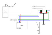
If the same GM500 is to work BOTH signal heads then this is done by just one set of change-over contacts on the GM500.
Feed ideally 12volts DC positive from a Regulated power supply to the GM500 Pad 1. From Pads 2 & 3 connect two wires to each. From Pad 2 take one wire to the left hand signals Green aspect wire. Take the other wire from this Pad 2 to the right hand signals head Red aspect wire.
From Pad 3 take one wire to the left hand signals Red aspect wire and the other wire on Pad 3 to the Right hand signal heads Green aspect.
So now that only leaves the two signals return wires. Each of these wires should connect to a series resistor of 1K0 (1000 Ohm) it doesnt matter which way around the resistors are wired to the return wires as resistors are not polarity sensitive. Join together the two free ends of the two resistors to one wire and that wire goes directly to the power supply Negative connection.
What you have now is automatic aspect switching of both signal heads controlled by the GM500 and the points position. Straight route left hand signal shows green while the right hand one shows red. Move the point over and the two signals swap aspects with the left hand one showing green and the right hand red. If you want the opposite sequence swap around the wires on Pads 2 and 3 only.
Here is the wiring
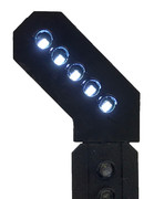
Technically the signalling method above is not normally used on BR lines. A single signal head with a Junction Indicator (Feather) on top of the signal head is used. The signal shows a proceed aspect for both routes and for the turn out direction the J/I also illuminates with a row of white lights.
Left hand divergence Junction Indicator (Feather) illuminating Position 1....
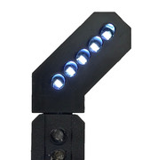
Right hand divergence Junction Indicator (Feather) illuminating Position 4...
If the same GM500 is to work BOTH signal heads then this is done by just one set of change-over contacts on the GM500.
Feed ideally 12volts DC positive from a Regulated power supply to the GM500 Pad 1. From Pads 2 & 3 connect two wires to each. From Pad 2 take one wire to the left hand signals Green aspect wire. Take the other wire from this Pad 2 to the right hand signals head Red aspect wire.
From Pad 3 take one wire to the left hand signals Red aspect wire and the other wire on Pad 3 to the Right hand signal heads Green aspect.
So now that only leaves the two signals return wires. Each of these wires should connect to a series resistor of 1K0 (1000 Ohm) it doesnt matter which way around the resistors are wired to the return wires as resistors are not polarity sensitive. Join together the two free ends of the two resistors to one wire and that wire goes directly to the power supply Negative connection.
What you have now is automatic aspect switching of both signal heads controlled by the GM500 and the points position. Straight route left hand signal shows green while the right hand one shows red. Move the point over and the two signals swap aspects with the left hand one showing green and the right hand red. If you want the opposite sequence swap around the wires on Pads 2 and 3 only.
Here is the wiring
Technically the signalling method above is not normally used on BR lines. A single signal head with a Junction Indicator (Feather) on top of the signal head is used. The signal shows a proceed aspect for both routes and for the turn out direction the J/I also illuminates with a row of white lights.
Left hand divergence Junction Indicator (Feather) illuminating Position 1....
Right hand divergence Junction Indicator (Feather) illuminating Position 4...
 << Click the Icon to go to my website
-
airfix27ra
- Posts: 54
- Joined: Sat Apr 25, 2020 12:36 pm
- Contact:
Re: Gaugemaster GM500 upgrade?
Hi Brian.
Right I think I have got it. Yes I will have to switch wires around as I need the right hand to be on green, left hand red,
changing when I switch point.
I will be using the signals for the train leaving the station pull in, to get back onto the main line.
Thanks, I will probably need a few more reads first. At least now I can get some GM500.
Brian, I would not worry about the accuracy of the signals. Hardly any of my layout is what it would be like in the real world,
I just like running trains around. The odd Metcalf kit here and there, a few cars and people etc. I'm happy. Real railway
modelers would probably have a fit looking at my layout, who cares, I don't, it works, sort of and that is the main thing.
Once again thanks very much for sharing your knowledge with me, a plebe (in modeling terms).
Hang on, I have just thought of something, as they are already wired of the way I want, don't I just need to add the resistors to
the two wires coming from the terminal block to the switch I have already, just putting the GM500 in place of the switch?
I would obviously need to play around to find which wire goes to pad 2or 3. Or am I missing something.
Stuart
Love, Peace and Happiness.
Old Hippies never die, we just float away.
Have a cup of tea. reference to Gong.
Old Hippies never die, we just float away.
Have a cup of tea. reference to Gong.
Re: Gaugemaster GM500 upgrade?
Hi Stuartairfix27ra wrote: ↑Thu Jun 11, 2020 12:56 pm Hi Brian.
Right I think I have got it. Yes I will have to switch wires around as I need the right hand to be on green, left hand red,
changing when I switch point.
I will be using the signals for the train leaving the station pull in, to get back onto the main line.
Thanks, I will probably need a few more reads first. At least now I can get some GM500.
Brian, I would not worry about the accuracy of the signals. Hardly any of my layout is what it would be like in the real world,
I just like running trains around. The odd Metcalf kit here and there, a few cars and people etc. I'm happy. Real railway
modelers would probably have a fit looking at my layout, who cares, I don't, it works, sort of and that is the main thing.
Once again thanks very much for sharing your knowledge with me, a plebe (in modeling terms).
Hang on, I have just thought of something, as they are already wired of the way I want, don't I just need to add the resistors to
the two wires coming from the terminal block to the switch I have already, just putting the GM500 in place of the switch?
I would obviously need to play around to find which wire goes to pad 2or 3. Or am I missing something.
Stuart
I dont quite understand your last comments from "Hang on " etc especially.... "Resistors to the two wires coming from the terminal block to the switch" ??? I don't know how you have wired them??
Assuming the signals are LED lit and they are wired as common Cathode (Negative) in the signal head, then each signal head will have three wires - Two are the positive to the two aspects and each signal head will also have a return negative wire, the LEDs in each of the signal heads are wired together internally on their negative side so one return wire/connection is provided per signal head. Each return wire is kept separate and a series resistor wired to each return wire, then the two resistors other ends are joined together and goes off to the power sources Negative.
How the positive feeds to each aspect per head is switched will depend on how you want it to work = Manually then via a SPDT switch or automatically via the points position and using one side of a GM500 contacts.
<< Click the Icon to go to my website-
airfix27ra
- Posts: 54
- Joined: Sat Apr 25, 2020 12:36 pm
- Contact:
Re: Gaugemaster GM500 upgrade?
Hi Brian
I have just got under the base board to refresh my memory, the signal is wired thus.
There are six wires coming from the base of the signal, two red and two green, each one of those four coloured wires has a resistor and two
ground or negative wires. The wires with the resistors are paired off each, one red, one green, each pair going into one of the blocks
the two negative wires are also paired and go into another block which is connected to the common return wiring. The two pairs of
wires with the resistors, then, via a pair of wires coming from the terminal block, connect up to my switch. Ah I think I explained it
wrong, I did not mean one single wire to the switch. What I should have said, was a single wire from each of the blocks containing the
red/green pairings. So therefore if a place a resistor(2000 Ohm, if they make one in that size) to each of the wires going to the GM500 tabs it should work, or will I have to use two 1000 Ohm resistors.
It is hard to see the diagram you sent, but looking at it again it seems as if the red/green wires (going to the GM500) have no resistors and just the negative have wires have them, is that right? If that is so, then all I have to do, is to remove the resistors from the red/green wires and
connect them to tabs 2 & 3 on the GM500 and place a resistor in the negative return wire, yes?
Sorry, I confused the issue, in my defense, I did say that I am not very good at explaining things in writing.
Hope this is ok.
Stuart
Love, Peace and Happiness.
Old Hippies never die, we just float away.
Have a cup of tea. reference to Gong.
Old Hippies never die, we just float away.
Have a cup of tea. reference to Gong.
Re: Gaugemaster GM500 upgrade?
You must have as a minimum one resistor per signal head therefore 2 heads = 2 resistors minimum.
There is really no need for these resistors to be in the feed wires, which then means you'll need four resistors. IMO that is just wasteful and unnecessary.
As only one LED can illuminate at any one time per signal head, the two aspects per head can share one resistor fitted in the return wire from each signal head
You should be able to click on the drawing and see it larger. There is also an option to download the drawing (upper left)
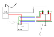
You're correct, the feed wires from the GM500 have no resistors in them (see above re not necessary) they run from GM500 pads 2 and 3 to the signal heads aspect leads. The two resistors are wired into one into each signal heads return wire, then the resistors are jointed at their other end and that is taken to the supply negative.
However, you can if you don't wanted to alter the wiring, continue using four resistors. Simply then connect each wire from GM500 pads 2 & 3 to the free end of the four resistors. The other end of each resistor being connected to the red or green wire that feeds the signals aspects.
The two return wires are then connected together and go to the supply negative. Wired like this..
There is really no need for these resistors to be in the feed wires, which then means you'll need four resistors. IMO that is just wasteful and unnecessary.
As only one LED can illuminate at any one time per signal head, the two aspects per head can share one resistor fitted in the return wire from each signal head
You should be able to click on the drawing and see it larger. There is also an option to download the drawing (upper left)
You're correct, the feed wires from the GM500 have no resistors in them (see above re not necessary) they run from GM500 pads 2 and 3 to the signal heads aspect leads. The two resistors are wired into one into each signal heads return wire, then the resistors are jointed at their other end and that is taken to the supply negative.
However, you can if you don't wanted to alter the wiring, continue using four resistors. Simply then connect each wire from GM500 pads 2 & 3 to the free end of the four resistors. The other end of each resistor being connected to the red or green wire that feeds the signals aspects.
The two return wires are then connected together and go to the supply negative. Wired like this..
<< Click the Icon to go to my website-
airfix27ra
- Posts: 54
- Joined: Sat Apr 25, 2020 12:36 pm
- Contact:
Re: Gaugemaster GM500 upgrade?
Hi Brian
YES, This is exactly how the signal are wired at present, with four resistors, now if I understand, you mentioned something about 1000 Ohm.
Is this value related directly to switching the signals via the GM500, rather than the toggle switch I am presently using.
Does that mean each resistor is 500 Ohm, as two wires are joined together.
Would it be simpler, if I removed the resistors from the LED wires and then added a resistor to the return wire. Would the 1000 Ohm resistor
be for each of the return wires, or for the pair. If for each wire, then it would be easier for me to buy a 2000 Ohm, combine the two wires
and use that.
I will contact CR Signals tomorrow and ask what value the resistors are.
I hope the penny has finally dropped with me. Famous last words.
Stuart
Love, Peace and Happiness.
Old Hippies never die, we just float away.
Have a cup of tea. reference to Gong.
Old Hippies never die, we just float away.
Have a cup of tea. reference to Gong.
Re: Gaugemaster GM500 upgrade?
If you're using 12 volt DC supply then usually a 1K0 (1000) Ohm series resistor will give a good general current limiting. Higher Ohm values such as 2K0 or above won't hurt. but they will though reduce the LEDs brightness.
The resistors have nothing to do with GM500 or any other form of switching. They are there to reduce the current flow to the lit LED.
I suggested 1K0 1000 Ohm either one in each signals return wire (2 needed) or in your case one in each signals feed wire (4 needed). No the resistors do not give 500 Ohm, they are 1000 ohm each and only one is used per lit aspect regardless of 2 or 4 resistors being used.
You cannot combine both aspect heads and use one resistor, do not try to do so. Treat each head as a individual signal.
Its entirely up to you how you install the resistors regardless of value 1K0 or higher ohmage. If you want four resistors then wire each resistor into the feed wire to each aspect. If you want to have two resistors wire then wire one into each return wire and then after the resistors join their ends and connect to the supply negative. Which ever method is used you can only ever have one LED lit in a head at one time.
Both methods work 2 resistors or 4. Just that 4 isn't really necessary. The two drawings show both options.
<< Click the Icon to go to my website