Page 170 of 201
Re: WEST ORTON
Posted: Wed Nov 13, 2024 4:11 pm
by Brian
Walkingthedog wrote: ↑Wed Nov 13, 2024 2:06 pm
And your ping pong equipment.
Brian I seem to recall a similar way of tensioning telephone wires.
Hi Brian. Yes these were telephone wires - 200lb copper. The UK railways had/still has the second largest telecoms system in the UK. The former GPO was the largest. The railways used pole routes for telephone connections, block signalling controls and to provide power to remote signals, such as motor driven distant semaphore signals and colour light distant signal battery charging. Today, 650v AC power cables are used for signalling installations and Fibre Optic cables for telecoms.
Re: WEST ORTON
Posted: Wed Nov 13, 2024 4:43 pm
by Walkingthedog
Thankfully GPO wires only carried 50 volts but more when ringing. I can remember touching one with a wet ear at just the wrong time.
Re: WEST ORTON
Posted: Thu Nov 14, 2024 4:48 pm
by bulleidboy
I bet that gave you "ringing in the ears" Brian

Re: WEST ORTON
Posted: Thu Nov 14, 2024 5:27 pm
by Walkingthedog
Still doing it Barry.
Re: WEST ORTON
Posted: Sun Dec 01, 2024 10:37 am
by Steve M
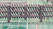
Latest bit of tinkering.
Got a bit greedy on length so it doesn't fit in my washer/curer! And a small issue with the base not sticking yo the build plate but the fence panel looks OK.
Re: WEST ORTON
Posted: Sun Dec 01, 2024 7:57 pm
by bulleidboy
Are you able to re-use any of the waste - there appears to be a lot for one length of fencing?
Re: WEST ORTON
Posted: Sun Dec 01, 2024 8:29 pm
by Steve M
No Barry, the supports are all waste.
The LMS fencing has a lot of conflicting angles and sticky out bits which make finding the 'right' orientation difficult. Bear in mind that you effectively print upside down and can't start a new section of print in mid air. Basically each layer must overlap the footprint of the previous layer of the print so it stays joined up. You also have to consider where the supports join the model so that as they are removed they don't damage the surface.
Take one of your 3D figures that is still supported and hold it upside down to get the idea.
I wasn't too fussed about this one as it's a proof of concept for the design and I have another section and the sloping fences for the platform ramps being printed at a shallower angle - again a test piece.
The old printer has also been fired up to try the fences with a different resin - they are too big for the printer!!
I suspect that providing the overhangs aren't a problem the fences may be better printed from one end hanging vertically from the printer or at a very slight angle from the vertical.
If I remember I'll take a screenshot when I prepare the file as it may help explain.
Designing in 3D on a 2D screen, then orientating the model in an alternative set of three dimensions guarantees a headache - slept through the F1.

But not as mind stretching as your control wiring.
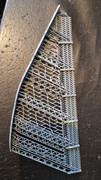
Re: WEST ORTON
Posted: Mon Dec 02, 2024 10:44 am
by Steve M
This may help to understand how the print is orientated and supported when it's being printed. You can see how the model hangs from it's supports with each layer just slightly offset from the previous one. At least that's the theory.
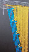
And this is a batch of straight sections ready for 'cooking'. 26 hours at 30c.


Re: WEST ORTON
Posted: Wed Dec 04, 2024 1:36 pm
by Steve M
Some extra detail. In reality the padlock is too fine, it actually hangs on the hasp but needs to be set back about 0.5mm.
Good enough for what I need.
Re: WEST ORTON
Posted: Wed Dec 04, 2024 1:55 pm
by Walkingthedog
That is incredible detail Steve.