Page 2 of 3
Re: Stay alive capacitor- wiring
Posted: Fri Mar 21, 2025 10:23 am
by Carl L
Witchcraft, totally agree, it bamboozles me at times. So, one naked decoder.
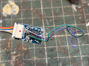
You know when a job is telling you to leave it - taking the A2 body off I managed to dislodge a smoke deflector hand rail and lose a knob. Black on a black floor, I think that’s gone for good

“Hello, is that Bachmann spares?”

Re: Stay alive capacitor- wiring
Posted: Fri Mar 21, 2025 11:47 am
by Steve M
Not obvious to me which is which, I think using the multimeter that Brian suggested would be a good idea.
Re: Stay alive capacitor- wiring
Posted: Fri Mar 21, 2025 12:13 pm
by Carl L
Apologies for this as this will seem like ‘electrics for dummies’ so,
‘with a multimeter switched to its DC voltage range of 20v or greater and see which of the two wires is the Positive’,
I take it I apply the multimeter probes to the green and purple wires, (do I?) how will it indicate which is the positive?
And some one is smiling down on me, I found the handrail knob

Re: Stay alive capacitor- wiring
Posted: Fri Mar 21, 2025 12:34 pm
by Steve M
Touch the wires with the probes from the meter. The display will read either -ve or +ve. Swap the probes round and the display should reverse. Trouble is, I can't remember if it's red or black that is the +ve side of the meter. Until Brian comes along you could work that out by using the probes on a battery.
Told you it was witchcraft.
Re: Stay alive capacitor- wiring
Posted: Fri Mar 21, 2025 12:40 pm
by Carl L
Complete and utter sorcery.
Re: Stay alive capacitor- wiring
Posted: Fri Mar 21, 2025 1:28 pm
by Brian
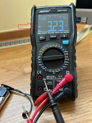
The red lead and red socket on the meter are Positive for DC readings. The Black lead and Black socket is the Negative. The meter will read either way around but as stated by Steve M when the red lead is on a positive supply the meter will show this is correct, if wrong way around it will show -ve or -
This shows a meter connected to a battery the right way around and then below the wrong polarity....

Note the - sign showing the leads are receiving the polarity the wrong way around.
Re: Stay alive capacitor- wiring
Posted: Fri Mar 21, 2025 2:11 pm
by cadman
The Blue wire from the decoder is a common positive return for all functions. The Purple wire is probably a flying lead with a negative polarity so if you connect your multimeter leads positive to the Blue wire and negative to the Purple wire you should get proof of circuit.


This shows a Hornby TTS decoder but illustrates the way of connecting the Stay Alive to the Bridge Rectifier noting that the positive can be connected to decoder's Blue wire instead.
These comments are given in good faith, maybe Brian can check validity.
Re: Stay alive capacitor- wiring
Posted: Fri Mar 21, 2025 2:41 pm
by cadman
Having given further thought I realise you cannot connect to the Purple wire because that is controlled by a decoder Function. The negative connection from the Stay Alive has to connect to the negative side of the Bridge Rectifier.
Re: Stay alive capacitor- wiring
Posted: Fri Mar 21, 2025 11:30 pm
by Hound Dog
I can almost smell the smoke from the decoder……..Alternatively you could always regularly clean the track, wheels and pick-ups…….. and avoid the sorcery and risk involved in wiring stay alives to some decoders……… this is written with the benefit of painful and expensive experience !
Re: Stay alive capacitor- wiring
Posted: Sat Mar 22, 2025 8:45 am
by RAF96
This thread talks to this decoder I reckon -
https://www.newrailwaymodellers.co.uk/F ... hp?t=56008
It notes the connector is a 7 pin only (no green wire to the plug) and that the purple and green wires are actually function outputs not stay alive connections, which if present would be red/black to match the stay alive.