Hello All,
This is all for the upcoming DCC system Brian convinced me to adopt.
I would like to wire in 24v LED panel lights to a mimic board from SPDT toggle switches.
I think I have a couple of problems though....
I have two iP digital point motors that will be running on regulated 12v DC....
My other point motors (DCC Concepts AE coil motors). On 24v DC. These motors together with the iPs all controlled by the SPDT toggles seperate from the actual mi ic board and its lights..
I am thinking to run the two12v motors to 12v panel lights and the 24v to the 24v lights keeping them seperate of course. Do I need resistors on the LEDs. . I am guessing yes but not 100% here.
Plenty of DIY mimic boards on the net but no wiring to lights from toggle switches.
Hope I am explaining my idea clearly here or my usual.......
Dirk
Mimic panel indicator lights.
-
Aussie 3 railer
- Posts: 124
- Joined: Mon Jul 15, 2024 2:24 am
- Contact:

Re: Mimic panel indicator lights.
Hi
Wiring LEDs to switches would only prove that the switch has moved, It doesn't prove the actual item controlled by the switch - point motor or the point etc has moved! You should only use momentary switches with solenoids - See below.
If the LEDs are sold as being rated at 24 volts and are operating at 24 volts, then they do not need any series resistor. It's built into the LED.
I have to admit you don't see too many LEDs suitable for panel indications sold as 24 volt operation! 12 volt or lower is more the norm.
DCC Concepts AE motors are solenoids and should be operated by momentary switches i.e. a non locking sprung to centre Off switch that are often referenced as (On)-Off-(On) type. On no account should you use a conventional On-On switch, as allowing power to remain On to the motor will quickly lead to the motors coil burning out! Adding a twin coil mechanical latching relay to the solenoids operation and return wiring allows for two electrically separate change over switch contacts that are ideal for LED indication operation. As an example, a ready-made latching relay is the Gaugemaster GM500 unit. https://www.gaugemasterretail.com/gauge ... witch.html
Of course, if the changeover contact on the AE motor is not being used for frog polarity, then that is ideal for operating panel indication LEDs. Some users like to use Point Position Indication (PPI) boards but again these like the GM500 and only prove that the switch has operated, not that the point motor has moved! Example of a PPI https://blocksignalling.co.uk/DC-Produc ... n-3mm-leds
 << Click the Icon to go to my website
-
Aussie 3 railer
- Posts: 124
- Joined: Mon Jul 15, 2024 2:24 am
- Contact:
Re: Mimic panel indicator lights.
Hello Brian,
Thank you for the quick reply and to the rescue as usual. The toggle switches are the on-off-on spring to centre 2 amp. I understand the LEDs don't remain on after switching on at the mimic board but I had another idea to overcome this using those small trackside lights (red green) things but a DIY version and wiring back to the mimic LEDs that way. It probably needs resistors being track voltage I guess or I go the other non preferred route of micro switches.
Advice here would be appreciated if you think it would work and suggestion if resistors are needed and size. At least I could just go with 12v LEDs all round at this rate.
Dirk
Re: Mimic panel indicator lights.
Hi Dirk,Aussie 3 railer wrote: ↑Mon Nov 03, 2025 12:40 am Hello Brian,
Thank you for the quick reply and to the rescue as usual. The toggle switches are the on-off-on spring to centre 2 amp. I understand the LEDs don't remain on after switching on at the mimic board but I had another idea to overcome this using those small trackside lights (red green) things but a DIY version and wiring back to the mimic LEDs that way. It probably needs resistors being track voltage I guess or I go the other non preferred route of micro switches.
Advice here would be appreciated if you think it would work and suggestion if resistors are needed and size. At least I could just go with 12v LEDs all round at this rate.
Dirk
Question...What is going to switch the LEDs between Red and Green or whatever LED colours are chosen? You have to use either the built in change-over contact fitted on the AE point motor, assuming it is not being used for Electrofrog polarity changing. Or use some other switching means, such as a micro switch operated by the point or the motors movement or use a mechanically latched relay connected to the point motors three operation wires.
"Trackside lights"? Do you mean Position Light Signals (sometimes called Shunt signals)? Like these for example https://www.amazon.co.uk/ARMYJY-Pieces- ... d_source=1 Whether ready-made or built yourself these still need their feeds to be switched somehow! So we are back to what sort of switching is to be used?
I think you need to look at how you intend to switch any power feeds going to either PLS or panel LEDs - both can of course be feed from the same point or point motor operated switch. Once this has been resolved then give us details of the LEDs to be used - a link is always good then we can advise on what resistance if any is needed.
<< Click the Icon to go to my website-
Aussie 3 railer
- Posts: 124
- Joined: Mon Jul 15, 2024 2:24 am
- Contact:
Re: Mimic panel indicator lights.
Brian,
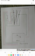
On the AE solenoid diagram it shows 3 terminals going from the switch end of the unit. The centre wire goes to the frog 2 other to the tracks. The other end of the solenoid to the toggle. It's those wires going to the track that I am thinking to connect to the LED's on the mimic board.
I am assuming the wire to the tracks would change with frog polarity and hopefully power the LED'S at the same time. Assuming of course they stay powered in that position until changed. Hopefully doing so ONE of the LED'S will also stay lit.
This stuff is wayout of my knowledge and I came up with this idea after a U tube video from The DCC guy, Larry Puckeridge. Videos 246 and 400.
Thanks for your time on this hopefully I am not wasting to much.
Dirk
[
-
Aussie 3 railer
- Posts: 124
- Joined: Mon Jul 15, 2024 2:24 am
- Contact:
Re: Mimic panel indicator lights.
Brian,
Haven't worried about the LED's in case this is a waste of time.
Failing the above post might just go with micro switches probably a lot easier in the long run.
Haven't worried about the LED's in case this is a waste of time.
Failing the above post might just go with micro switches probably a lot easier in the long run.
Re: Mimic panel indicator lights.
HiAussie 3 railer wrote: ↑Tue Nov 04, 2025 2:26 am Brian,
On the AE solenoid diagram it shows 3 terminals going from the switch end of the unit. The centre wire goes to the frog 2 other to the tracks. The other end of the solenoid to the toggle. It's those wires going to the track that I am thinking to connect to the LED's on the mimic board.
I am assuming the wire to the tracks would change with frog polarity and hopefully power the LED'S at the same time. Assuming of course they stay powered in that position until changed. Hopefully doing so ONE of the LED'S will also stay lit.
This stuff is wayout of my knowledge and I came up with this idea after a U tube video from The DCC guy, Larry Puckeridge. Videos 246 and 400.
Thanks for your time on this hopefully I am not wasting to much.
Dirk
[
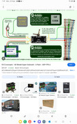
The two wires from the rails will be powered constantly on DCC and partially on DC. On DC they will also reverse polarity when the direction of travel is reversed. So are not suitable for any Indications where DC is concerned. On DCC you can use the frog output to a) Feed the frog and b) feed indication LEDs in the panel. But you will also need DCC powered feeds in the panel too. I show this here if its of help? https://www.brian-lambert.co.uk/DCC-Pag ... ndications The second drawing down shows a basic Electrofrog point with frog feed and LED indications.
<< Click the Icon to go to my website-
Aussie 3 railer
- Posts: 124
- Joined: Mon Jul 15, 2024 2:24 am
- Contact:
Re: Mimic panel indicator lights.
Hello Brian,
I think I am getting a handle on this finally....
Got some spare time coming up so might be able to have a trial run with this.
You certainly have spent some time on these tutorials. They are a great resource.
Dirk
I think I am getting a handle on this finally....
Got some spare time coming up so might be able to have a trial run with this.
You certainly have spent some time on these tutorials. They are a great resource.
Dirk
-
Aussie 3 railer
- Posts: 124
- Joined: Mon Jul 15, 2024 2:24 am
- Contact:
Re: Mimic panel indicator lights.
Hello Brian,
Just on the LED and resistors. I used your link and came up with this. The book photo with the Biro line was the one I was looking at. Thought this might give me something to do while out of action.
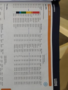
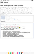
Just on the LED and resistors. I used your link and came up with this. The book photo with the Biro line was the one I was looking at. Thought this might give me something to do while out of action.