Advice on this Loop.

Help with designing your track work
Post Reply
Aussie 3 railer
Posts: 107
Joined: Mon Jul 15, 2024 2:24 am
Contact:

Advice on this Loop.

#1

Post by Aussie 3 railer »

Hello All,

Been a while since I have been here. Renonations and and a spot of ill health slowed me down.

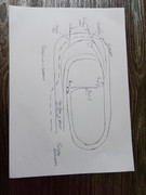
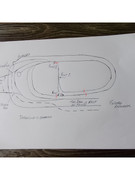
This current layout is one of so many other numerous layouts I have tried. Most were done away with for one reason or another. Peco must have been very happy with my efforts with the track I have bought.

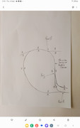
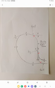
My problem with this one, I actually really like, is this loop which is beyond my expertise. I have included a mud map for reference rather me trying to explain as Brian suggested some time ago.

My problem is between points B and C in the diagram. This is where the polarity changes for my bit. The distance between B and C is about 900mm plus. All my rolling stock have or will have plastic wheels so I am figuring no shorts here and plus none of my trains will be multiple cars.

I have a few options here but my preference would be to use NO / NC contact switches as a means of wiring a possible solution. I am waiting on DCC Concepts to start production again on the Cobalt SS point controllers..... I have a couple of IP Digital controllers I was initially going to usevuntil I saw the Cobalt SS controllers. So depending on your advice I am happy to use them temporarily for the moment or whatever. I have an idea to use them above board.

At this moment I will be using manual point conrols while I wait for DCC.

In my spare time I have been making my own points after encouragement by Rick of DCC. I have learned a lot and learned not to paint the sleepers and to stain them. Found it very rewarding and to date all have tested out rather well.
Image
User avatar
Stese
Posts: 381
Joined: Thu Oct 04, 2018 9:26 pm
Location: UK
Contact:

Re: Advice on this Loop.

#2

Post by Stese »

Hi Aussie,

Since you are building what looks like a reverse loop, you might find the information on the following link, of use.

Brian Lamberts Website - Electrical, Page 3

if you are unsure, Brian may be able to provide further clarification... :)

Regards,

Steve D.
Father, IT Guy, HO/OO Modeler.
User avatar
Brian
Posts: 2312
Joined: Thu Oct 04, 2018 3:49 pm
Location: SE Kent
Contact:

Re: Advice on this Loop.

#3

Post by Brian »

Hi
Here's my take on the reverse loop. However, a lot depends on what happens track configuration wise after point C? But without that detail then.. Use six Insulated Rail Joiners (IRJs) a pair being fitted where I have shown each of the red lines cutting across the track (3 sites in all) The pair of IRJs on the upper track after point C can be pushed out much further along that track if wished. Feed the rails between the IRJs from a changeover pair of contacts - A DPDT Toggle switch is simplest, but you need to remember to flip the switch as necessary. Of course DCC is much simpler by using a Reverse Loop Module for the feeding of the section between the IRJs.
Image

BTW don't rely on all stock having plastic wheel sets, ideally, these need upgrading to metal wheels. But also you may in the future obtain a new item that will have metal wheels anyway!
Image << Click the Icon to go to my website
Aussie 3 railer
Posts: 107
Joined: Mon Jul 15, 2024 2:24 am
Contact:

Re: Advice on this Loop.

#4

Post by Aussie 3 railer »

Hello All,

Thank you Steve for Brians link. He sure does some incredible work. I hadn't seen this one.

Regards Dirk.
Aussie 3 railer
Posts: 107
Joined: Mon Jul 15, 2024 2:24 am
Contact:

Re: Advice on this Loop.

#5

Post by Aussie 3 railer »

Thank you Brian for your connection assist. No idea what was going on there but all good again.

On the loop problem I think I am going to abandon the DC bit as its not going to achieve what I thought it might SO going to the dark DCC side..... your comment swayed me.

I have attached another rough plan of my layout. In regards to you suggestion to push the isolaters out past your marked position I can move them out another 1m from point B to the left toward the turntable etc.. After that there are several other points going to various locations. Turntable, fiddle yard and shed track I haven't shown and not fitted yet.

The area I have marked as a maze of points is about the end of work to date. Most of the points are running into point A eventually.

All my points are insulated head and toe. I got sick of destroying them changing layouts. Point ends and track connections are all PCB and screwed. They also have their own droppers and are wired head end as your idea earlier articles.

Is it allowed to post DCC plans.

Regards Dirk


Image
User avatar
Brian
Posts: 2312
Joined: Thu Oct 04, 2018 3:49 pm
Location: SE Kent
Contact:

Re: Advice on this Loop.

#6

Post by Brian »

Hi
With DCC things are so much simpler! Personally, I would now fit 8 IRJs two each in the four places marked and feed the rails after point B and before point C from the output of a Reverse Loop Module. Input to the module is from the main DCC Bus pair or any rails feed directly from the DCC System.


Image
Image << Click the Icon to go to my website
Post Reply