Dead Locos

-
Walkingthedog

- Posts: 5119
- Joined: Thu Oct 04, 2018 5:51 pm
- Location: HAZLEMERE, BUCKS.
- Contact:
Re: Dead Locos
As far as I can see you haven’t told us what make the locos are, perhaps I missed where you said it.
Nurse, the screens!

Re: Dead Locos
Graham Farish from c. mid 70s I'd guess.
Looking at connectivity it looks like power has to get through a number of dry joints;
. the number of fishplates from the nearest dropper
. track to wheels (x2)
. wheels to copper fingers (x2)
. copper to brass contacts
. brass contacts to motor brushes
So I can see why everything would need to be scrupulously clean for this to have any chance of working.
All N Gauge

Re: Dead Locos
if you have a multi meter, it should be able to show you if you do have connectivity issues
Father, IT Guy, HO/OO Modeler.
-
GeoffAlan2
- Posts: 89
- Joined: Sat Oct 06, 2018 1:57 pm
- Contact:
Re: Dead Locos
Butch wrote: ↑Sat Nov 28, 2020 5:09 pm Well I've just opened one up. It has Graham Farrish cast into the bottom and I see that they are fairly common. So the motor spins up a jack shaft that then drives a shaft that runs the length of the chassis under that with worm drives on each of the end axles. The step down gearing on all of this is quite big.
First point is that the motor is attached at the top with double sided tape. This seems to have let go. So question is - what is the best way to reafix this? Some kind of tape or maybe an adhesive? Also there seem to be any number of electrical connections here that are little more than pressed contact. I'd imagine the current draw shouldn't be too demanding but if there is much corrosion here then nothing much is going to work.
Double side tape will do the job. Remove the old tape and make sure there's no oil about. cut new piece of tape to size and apply.
-
Walkingthedog
- Posts: 5119
- Joined: Thu Oct 04, 2018 5:51 pm
- Location: HAZLEMERE, BUCKS.
- Contact:
Re: Dead Locos
Are you sure motors are held in place with tape. Pretty sure locos of that age were not.
Nurse, the screens!

Re: Dead Locos
I googled Farish service sheets both old and new yesterday - and without fail the motors were secured by clips or lugs in the chassis. Any tape would surely be there only for insulation? The chassis are often ‘live’ which is one reason why they are tricky to convert to DCC requiring insulating sleeves for fixings.Walkingthedog wrote: ↑Mon Nov 30, 2020 12:13 pm Are you sure motors are held in place with tape. Pretty sure locos of that age were not.
Going back to testing, start by connecting the power supply direct to the motor terminals to see if it turns then work back from there through the internal wires to the pickups and wheels. A PP3 9v battery is good for this.
"Not very stable, but incredibly versatile." 
-
Walkingthedog
- Posts: 5119
- Joined: Thu Oct 04, 2018 5:51 pm
- Location: HAZLEMERE, BUCKS.
- Contact:
Re: Dead Locos
OK. I've just opened up another one. Not quite as clean inside as the first one, but I'll try and put up some pics.
All N Gauge
Re: Dead Locos
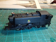
OK. I see pic posting is working. So that first one was as it came.
Here's the underside with the Graham Farish moulding inthe plastic chassis and the single screw that holds the top on. And here is the inside of the top once that screw is removed.
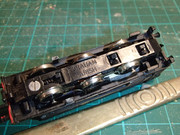
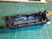
Here's the underside with the Graham Farish moulding inthe plastic chassis and the single screw that holds the top on. And here is the inside of the top once that screw is removed.
All N Gauge